
Writing a Shader Graph
May 6, 2020
Recently I wrote a shader graph / material editor for Hyde & Seek, a 30-week-long game project built in a custom engine using C++.
Introduction
A shader graph is a graph network representing a shader/material. It presents a node-based graph interface that enables designers & artists to add and connect nodes to create a shader without having to write any code.
https://blogs.unity3d.com/2018/03/27/shader-graph-custom-node-api-using-the-code-function-node/
https://docs.unrealengine.com/en-US/GettingStarted/SubEditors/index.html
One thing that I really liked in Unity/Unreal is their shader graphs, which makes creating new materials a lot easier. And so when we embarked on our new project, it was one of the first features I wanted to add to our custom engine/editor, and one of the first features I prototyped independently.
Here’s a little snippet of the shader graph in our engine, showing off a fake water material used for a level:
Constraints
Writing a shader graph is hard. For one, there is a distinct lack of examples and resources on the web. Examples you can find are also typically too complex to be suitable for school projects.
Since the project was only 30 weeks long, and the first half was dedicated to the engine/editor, I needed a simple, easy-to-implement design, as it wasn’t the only responsibility I had (I was also in charge of reflection/serialization, particle systems, UI systems/tools, some editor features, as well as gameplay scripting.)
In this article I will present how I made it work, and the losses I had to cut.
How does it work?
The basic idea is: a shader graph is a graph representation of a fragment shader (in my case, GLSL).
Each node in this graph is a text block in the GLSL code.
For example, the Multiply node takes in 2 floats/vectors and spits out the multiplied output.
In GLSL form it would simply be <out0> = <in0> * <in1>;.
Then, during the graph compilation we simply lay out these chunks appropriately to form the program.
Each graph has a master node, which is the final output of the shader graph.
To compile, we simply start from the master node, and recursively walk the inputs (pre-order traversal). That means that if the input node is unresolved, we resolve it by walking the input node’s inputs. We do this until the master node is resolved.
Compilation example
As an example, let’s look at the shader graph shown below.
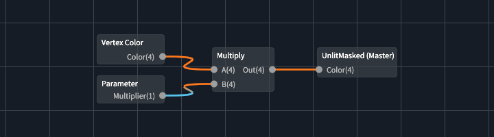
During compilation, we…
- Try to resolve UnlitMasked (Master).
- Resolve first input Color.
- Resolve node Multiply.
- Resolve first input A.
- Resolve node Vertex Color.
- Create output variable for output slot Color
var1. - Append resolved code
vec4 var1 = fs_in.color;
- Resolve second input B.
- Resolve node Parameter - Multiplier (this is a shader uniform!)
- Create an output variable for Out
var2. - Append resolved code
vec4 var2 = var1 * vec4(param_Multiplier);
- Resolve first input A.
- Resolve node Multiply.
- Append master node code
FragColor = var2;
- Resolve first input Color.
And this is what the output fragment shader might look like:
#version 450

// other uniforms/attributes here...

uniform float param_Multiplier;

out vec4 FragColor;

void main()
{
   // pre code...

   vec4 var1 = fs_in.color;
   vec4 var2 = var1 * vec4(param_Multiplier);
   FragColor = var2;

   // post code...
}
Unless you dedicate effort to making the generated output clean, in practice, it won’t look as clean and tidy.
Some nodes will also have multiple output slots, leading to unused variables. However, that’s okay, as they should be optimized out when the GLSL is compiled.
Pseudocode
function resolve_node(node):
    let input_code = ""
    let this_code = node.code
    store_outputs(node) // create variables for each output
    for i in node.inputs:
        if i.connected_node is resolved:
            replace(this_code, i, i.connected_output)
        else:
            input_code += resolve_node(i.connected_node)
            replace(this_code, i, i.connected_output)
        return input_code + this_code

let output = resolve_node(master_node)
Data-Oriented Design
Before I delve deeper I want to explain a little about the design choices. The entire shader graph is done in a data-oriented fashion. The graph simply holds data on the nodes and links, the Shader Graph editor creates and modifies the graph, and the Shader Graph Compiler takes in the data and spits out a fragment.
Node Format
Particularly, I came up with a simple text format to specify the nodes. This is in contrast to online projects I saw where each node was a class. Doing it in such a data-oriented manner meant that:
- nodes could be implemented quickly, and
- nodes could be modified or added without recompilation of the engine.
For sake of reference, here is what Multiply.node looks like:
float,float->float
vec2,vec2->vec2
vec3,vec3->vec3
vec4,vec4->vec4
A,B,Out
{2} = {0} * {1};
(It can be argued that the 4 lines of type signatures can be collapsed to 1 line, but I didn’t see it as a worthwhile effort.)
Structures
As previously mentioned, the graph simply holds data. Nodes and links are all also pure data. This also makes it much easier to serialize/deserialize.
enum class ValueType
{
    FLOAT = 1, VEC2, VEC3, VEC4, SAMPLER2D, INVALID = 0
};

struct Slot
{
    ValueType type{};
    string value; // if unconnected
};
struct Node
{
    string name;
    Guid guid;
    vec2 position;
    vector<Slot> input_slots;
    vector<Slot> output_slots;
};
struct Link
{
    Guid node_out;
    Guid node_in;
    int slot_out{};
    int slot_in{};
};
struct Parameter
{
    string name;
    ValueType type{};
    string default_value;
};

struct Graph
{
    Guid master_node;
    hash_table<Guid, Node> nodes;
    vector<Link> links;
    vector<Parameter> parameters;
};
Editor
Our editor uses Dear ImGui, and the Shader Graph editor specifically uses ImNodes, which is a node graph implementation for Dear ImGui. Some drawing functions in ImNodes were then overwritten to make the nodes visually cleaner.
I first tried using imgui-node-editor, but it was too specific. Later on in development when I was revamping the Shader Graph editor, I tried out imnodes but it was too late to be worthwhile.
Truth be told, for a huge chunk of the development of Hyde & Seek, the Shader Graph editor was not very usable. It was inconvenient and user-unfriendly. When I got a basic, usable-enough version up, I stopped working on it for a long time, focusing on other engine/editor features instead. And to be fair, it was not used much until later in development.
Type Conversions
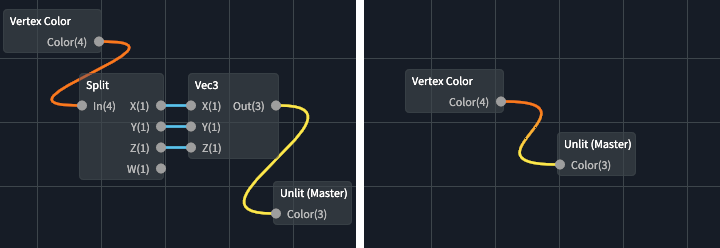
A large part of the user-unfriendliness stemmed from the fact that there was no type conversion.
For example, let’s say you wanted to wire a vec4 output into vec3 input – you couldn’t!
The only way was to use a Split node to split the vec4 into X, Y, Z & W,
then use the Vec3 node to combine X, Y & Z. Therefore, I had to implement
automatic type conversions.
GLSL float/vector conversions
Before discussing the automatic type conversion, here is a little primer on typecasting in GLSL.
- To typecast in GLSL, simply use the constructors.
- E.g.
vec2 aVec2 = vec2(aVec4);
- E.g.
- A vector can be casted to any dimension lower.
- E.g.
vec4can be casted tovec3,vec2&float.
- E.g.
- Only floats can be casted to any dimension higher, which sets each component
in the vector to the float (i.e. a fill constructor). Vectors cannot be casted any dimension higher
because they require arguments for the missing components.
- E.g.
vec3(1.0)produces (1, 1, 1), butvec3(aVec2)is illegal (what value do you use for the z-component?).
- E.g.
Type matching
With the points above, we can build a simple function for type matching:
TypeMatch type_match(int t1, int t2)
{
    if (t1 == t2) return TypeMatch::Match;
    if (t1 == ValueType::SAMPLER2D || t2 == ValueType::SAMPLER2D) return TypeMatch::None;
    if (t2 < t1) return TypeMatch::Downcast;
    if (t1 == ValueType::FLOAT) return TypeMatch::Upcast;
    return TypeMatch::None;
}
Here upcast means to cast to a higher dimension, and downcast means to cast to a lower dimension.
Overload Resolution
Type matching, however, is not enough.
Imagine if a Multiply node’s A input slot is currently connected to a vec3 value.
Then it’s input slot B must take in a vec3 value too.
Now imagine you wanted to connect a vec2 value into the B slot.
If you just used type matching, it would clearly fail. However,
the intended behavior is to swap the Multiply node to take in 2 vec2s instead
(because vec3 can be casted to vec2, but not vice versa).
Thus, for automatic type conversion to work properly, overload resolution must be implemented. Similar to overload resolution in C++, we match each parameter for every signature to determine the best matching function.
Recall Multiply.node:
float,float->float
vec2,vec2->vec2
vec3,vec3->vec3
vec4,vec4->vec4
A,B,Out
{2} = {0} * {1};
The first 4 lines are the function overloads.
float,float->float means it takes in 2 floats, and returns 1 float.
When a user connects a node’s output
to another node’s input, we apply overload resolution in order to select the best signature.
To do so, for each signature, we apply type matching for each parameter, and order the matches based on
priority: exact match is the highest priority, “upcast” is the second highest,
“downcast” is the third highest, and no match is the lowest. From there,
we simply compare each score against each other to find the best signature match.
Here is some pseudocode to better explain:
let best_match_values = []
for i in 0...inputs.size:
    best_match_values[i] = None

for sig in signatures:
    let curr_match_values = []
    for i in 0...inputs.size:
        curr_match_values[i] = type_match(inputs[i], signatures[i])
    sort_descending(curr_match_values)

    let is_better_match = true
    for i in 0...inputs.size:
        if curr_match_values[i] == None || curr_match_values[i] < best_match_values[i]:
            is_better_match = false
            break

    if is_better_match:
        best_match_values = curr_match_values
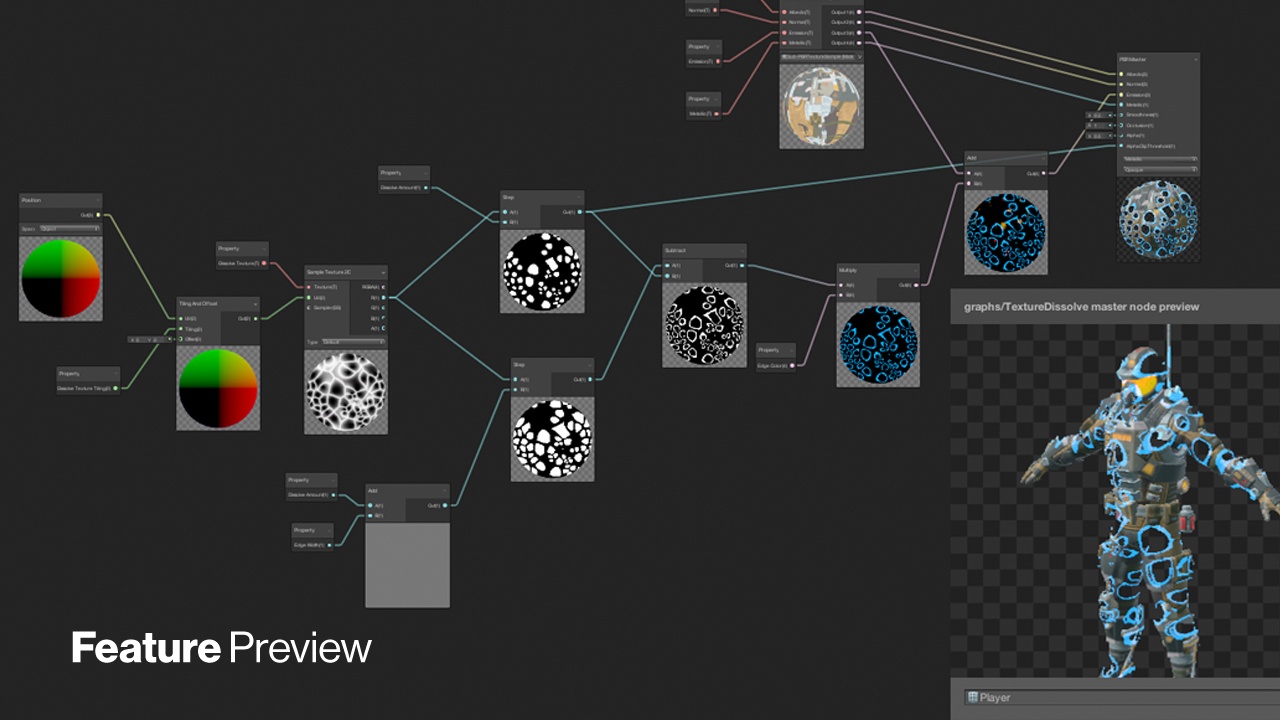
Node Previews
A node preview is a preview of the main output value at that stage of the graph. As an example, refer to the Unity Shader Graph image at the top of the article. While we didn’t get node previews up due to time constraints, I have a little insight into how they might work.
The first step is to generate a different shader for each incremental step in
the graph where you want a preview, cast the main output value of the current node
to a vec4 and return it as the (opaque) fragment output color, i.e. FragColor = vec4(last_output);
For a float value, this would result in a grayscale image, which is exactly what
you’d expect.
The second step is to actually render the previews. This is arguably the harder step as you have to integrate it with the graphics system, and you have to render an image for each preview.
Conclusion
Thank you for reading this article, and I hope it was helpful to you. Writing a shader graph had actually been a lot of fun for me, and there’s quite a lot of detail I’ve omitted to keep this article short and concise. However for those wanting or starting to write one, I hope that this is at least a good start!
If there’s any topic you’ve felt I missed, or any questions or feedback, feel free to comment.